Lighting control has come a long way. What started as a simple on-off switch has evolved into dynamic, intelligent systems capable of completely transforming a space. Whether you're setting a mood, building a smart home, or designing an immersive experience, lighting control is key.
And at the heart of modern lighting control is DMX.
This video dives into an introduction to DMX, example system design, wiring, and programming.
What is DMX?
DMX stands for Digital Multiplex. It’s a standardized, open-source digital communication protocol that enables remote control of lighting fixtures. Originally developed for stage lighting, DMX is now used across residential, commercial, and event installations.
Why DMX?
- Powerful: Enables granular control of lighting effects.
- Precise: Each fixture and channel can be fine-tuned.
- Versatile: Works for single-room installs or complex, multi-zone venues.
- Scalable: Excellent for everything from home automation systems to massive stage productions.
- Reliable: Wired signal minimizes interference.
- Compatible: Works across most professional-grade lighting systems.

Understanding DMX Channels and Addresses
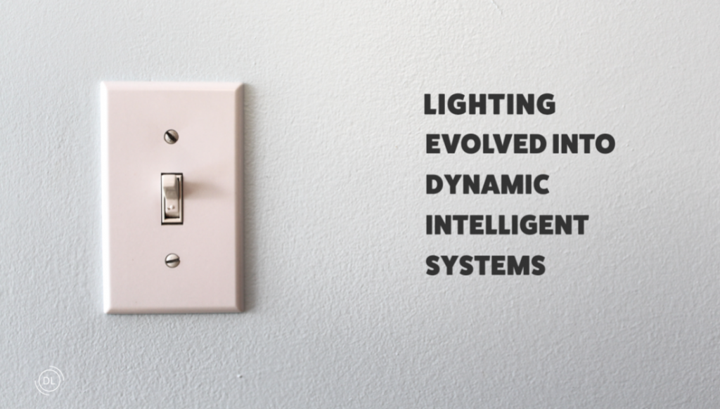
A DMX Universe consists of 512 controllable channels.
- Each fixture is assigned a starting address.
- The number of channels used depends on the fixture's capability.
- Each channel corresponds to a lighting attribute—e.g., color, brightness, effects.
Example: LED Tape Light Systems
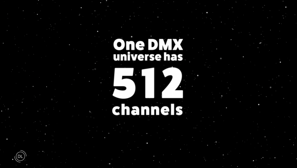
The number of DMX channels is based on how many control wires the LED tape has (excluding the power wire):
| Type | Wires | Channel Assignment |
| Static White | 2 wires | Ch. 1 = Black |
| Tunable White | 3 wires | Ch. 1 = Warm White, Ch. 2 = Cool White |
| RGB | 4 wires | Ch. 1 = Red, Ch. 2 = Green, Ch. 3 = Blue |
| RGBW | 5 wires | Ch. 1 = Red, Ch. 2 = Green, Ch. 3 = Blue, Ch. 4 = White |
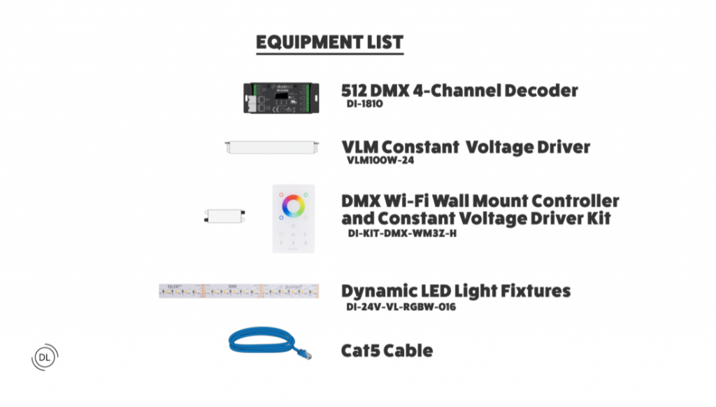
Essential Equipment for RGBW Tape Light Setup
To build a functional DMX lighting system, you can use some of the following Diode LED components:
Required Components
- 512 DMX 4-Channel Decoder
Converts DMX signal to usable output for RGBW fixtures. - VLM Series Constant Voltage LED Drivers
Powers each DMX decoder, ensuring stable output and avoiding flicker. - DMX Wi-Fi Wall Mount Controller & Driver Kit
User-friendly interface for scene selection and color control. - Valent RGBW LED Tape Light
Color-changing dynamic fixtures. - CAT5 Cable
Industry-standard wiring for linking DMX components.
Step-by-Step Installation Guide
1. Plan Your Installation
Choose installation locations for drivers, decoders, and tape light.
2. Turn Off Power at the Circuit Breaker
3. Connect DMX Decoder to Driver
- Each decoder connects to its own VLM driver.
- V+ (driver) → Power Input (decoder)
- V− (driver) → Ground/Return
4. Connect LED Tape to Decoder
Wire each RGBW tape fixture to its decoder:
| Wire Color | DMX Decoder Terminal |
| Red | R |
| Green | G |
| Blue | B |
| White | W |
| Black | V+ |
5. Connect Driver to High Voltage Power
Ensure a licensed electrician appropriately installs the VLM constant voltage LED driver to line voltage.
6. Daisy Chain Decoders via CAT5 Cable
- Use Input → Output ports.
- Max: 10 decoders per chain.
- Controller → DMX Decoder 1 → DMX Decoder 2 → DMX Decoder 3
7. Install DMX Wi-Fi Controller
- Connect CAT5 cable to controller and plug into DMX Decoder 1.
- Wiring convention:
- Brown = Ground
- Orange = D-
- Orange/White = D+
8. Turn Power Back On
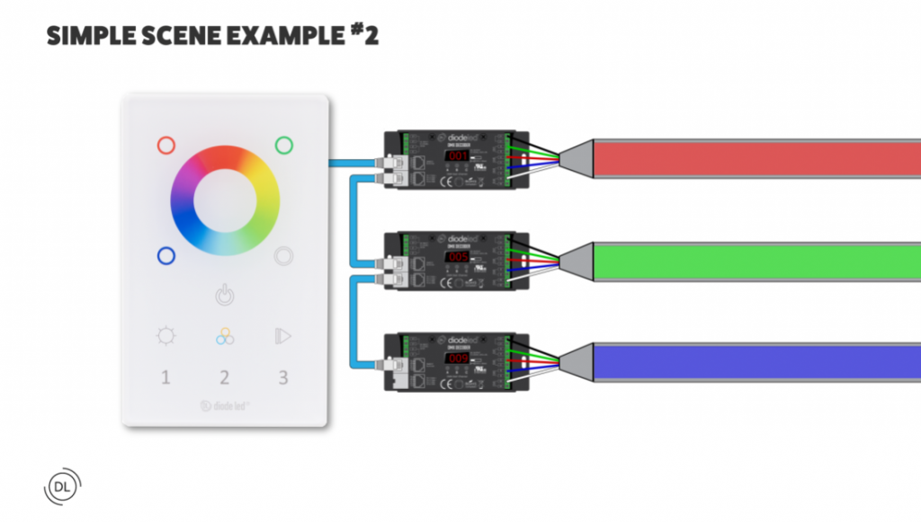
9. Assign Unique DMX Addresses
Each decoder must have a unique starting address:
- Fixture 1: Address 001
- Fixture 2: Address 005
- Fixture 3: Address 009
To set the DMX address:
- Hold Button 3 until display flashes.
- Use:
- Button 3 = single digits
- Button 2 = tens
- Button 1 = hundreds
- Hold Button 1 + 3 to reset if needed.
10. Test the System
Ensure all zones respond to commands. Check wiring if issues arise.
Scene Demonstration Examples
Example 1: Manual Color Selection
- Zone 1 → Red
Fixture 1 (Address 001) turns red. - Zone 2 → Green
Fixture 2 (Address 005) turns green. - Zone 3 → Blue
Fixture 3 (Address 009) turns blue.
Example 2: Auto-Cycle Effect
- Zone 1 → Play
Channels 1–4 cycle colors. - Zone 2 → Play
Channels 5–8 cycle. - Zone 3 → Play
Channels 9–12 cycle.
Example 3: Sync All Fixtures
- Tap Zones 1, 2, and 3 quickly, then select a color.
All fixtures sync to the same color.
Test your ability!
Now that you’ve learned the basics, you’re ready to explore more advanced scenes, multiple universes, or synchronized audio-light shows.